
|
 |
 |
 |
 |
|
|
|
MGL Avionic Glass Cockpit Stratomaster iEFIS MX-1
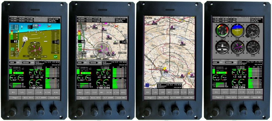
 Click on pictures to enlarge them.
Caution : dimensions of images on your computer screen depend on its resolution and may differ from actual iEFIS sceen dimensions.
The iEFIS "MX-1" (7" 177mm diagonal, WGA 480 x 800 pixels, portrait) ships since august 2019.
Since August 2020, the iEFIS "MX-1" can also be used in Landscape mode (7" diagonal, WGA 800 x 480 pixels, landscape).
Dimensions:
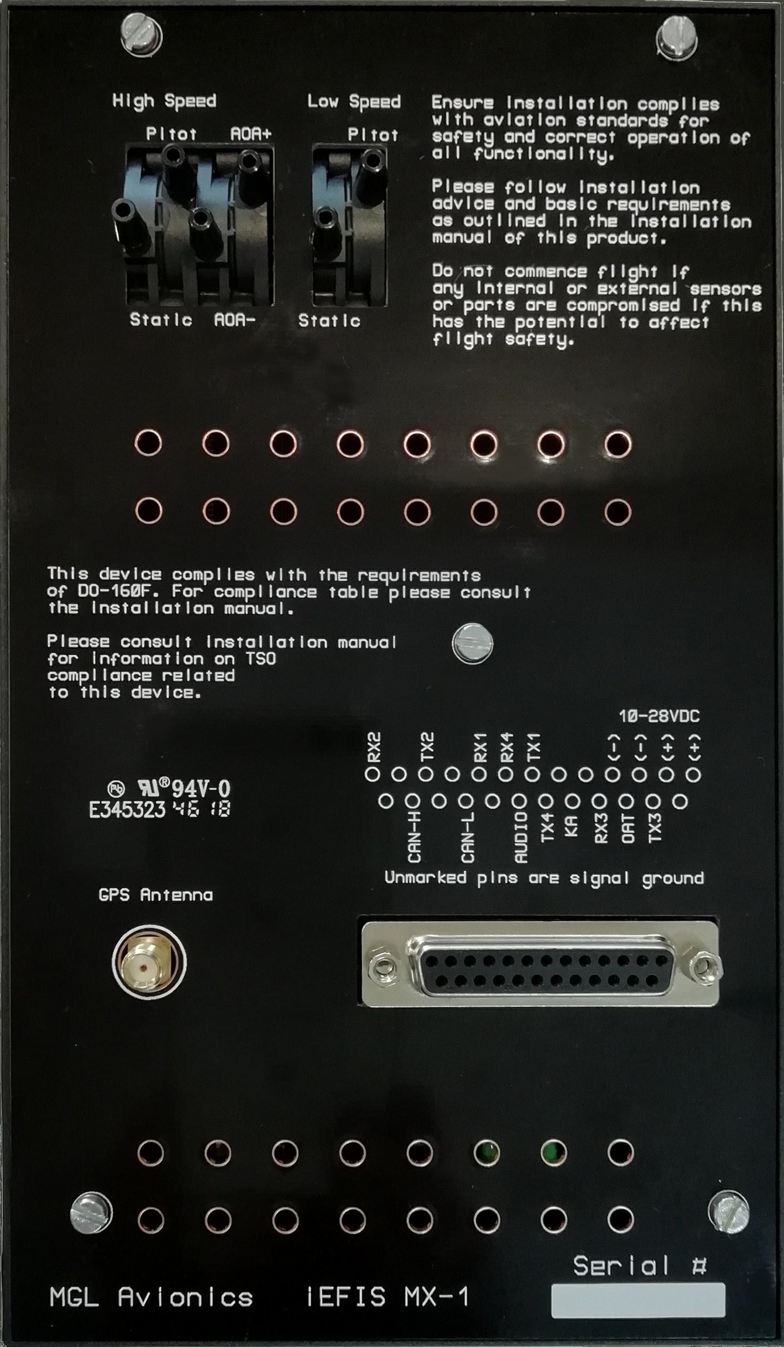
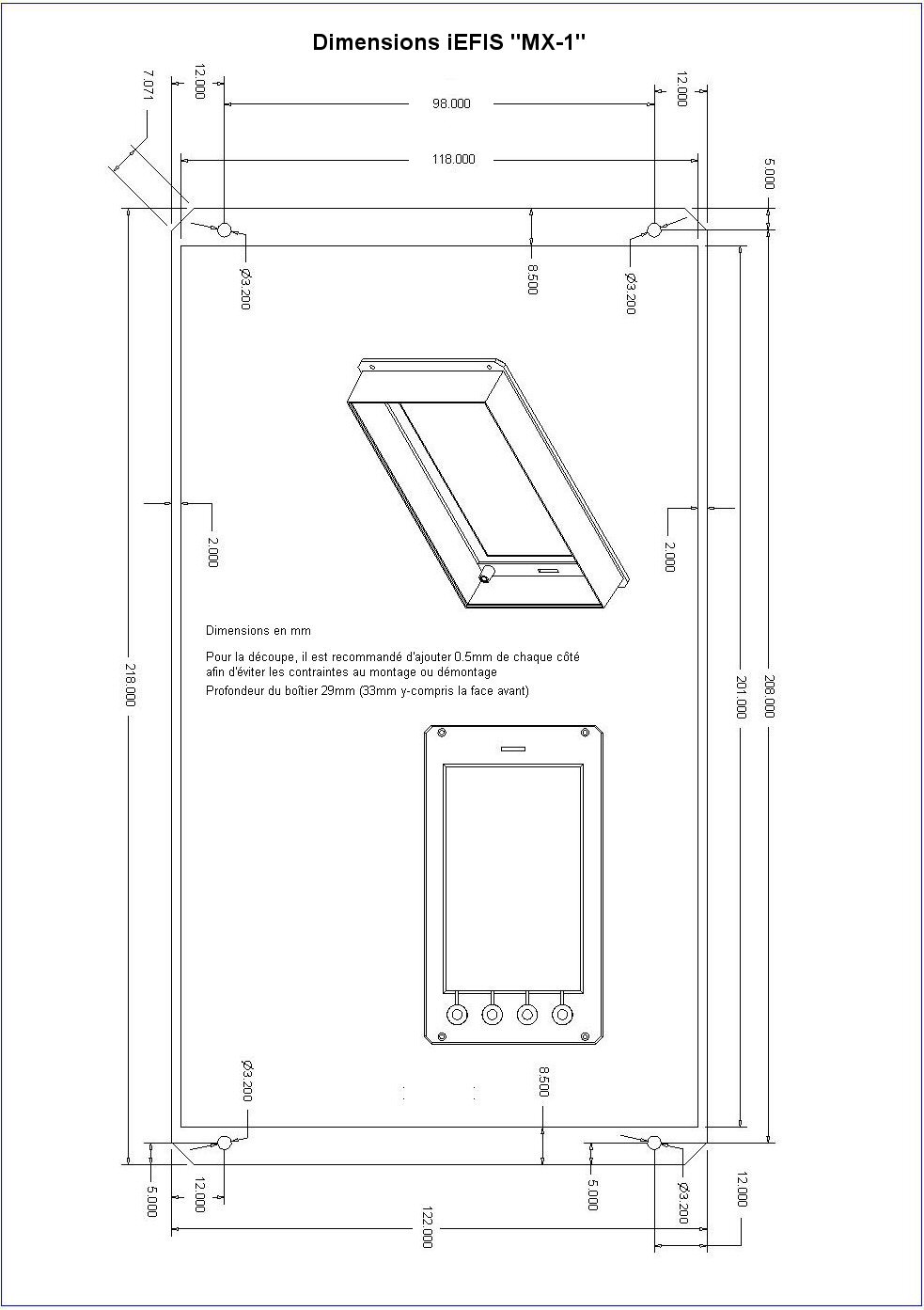
122 x 218mm, panel cut 118 x 201mm Download drawing
Weight: 700g approx.
Do you want to try an iEFIS? Its possible right now by downloading the simulation program (requires a PC running Windows NT, 2000, XP, VISTA, Windows7) which simulates the operation of the iEFIS.
The simulator allows you to almost fully operate a virtual iEFIS. Perfect for learning how to use it without using a physical instrument, at home or at your club!
"iEFIS MX-1 simulator" : Download installation program MX1Simulator.exe
Return to general description
|
MGL Avionic Glass Cockpit Stratomaster iEFIS Discovery Lite
 Click on pictures to enlarge them.
Caution : dimensions of images on your computer screen depend on its resolution and may differ from actual iEFIS sceen dimensions.
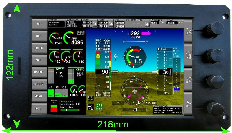
L'iEFIS DISCOVERY "Lite" (diagonale 177mm 7", WGA 800 x 480 pixels) ships since october 20th 2014.
Dimensions:
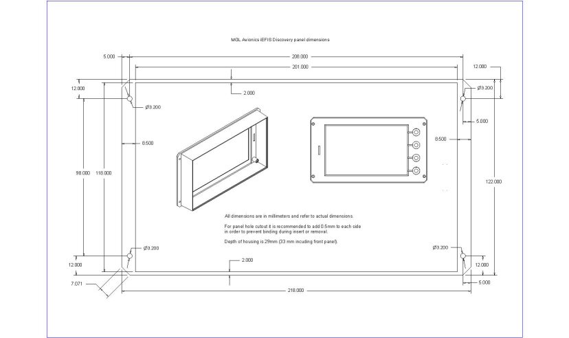
218mm x 122mm, panel cut 201 x 118mm Download drawing
Weight: 700g approx.
Do you want to try an iEFIS? Its possible right now by downloading the simulation program (requires a PC running Windows NT, 2000, XP, VISTA, Windows7) which simulates the operation of the iEFIS.
The simulator allows you to almost fully operate a virtual iEFIS. Perfect for learning how to use it without using a physical instrument, at home or at your club!
"iEFIS simulator"" : Download installation program iEFISG3Simulator.exe
Return to general description
|
MGL Avionic Glass Cockpit Stratomaster iEFIS Challenger
 Click on pictures to enlarge them.
Caution : dimensions of images on your computer screen depend on its resolution and may differ from actual iEFIS sceen dimensions.
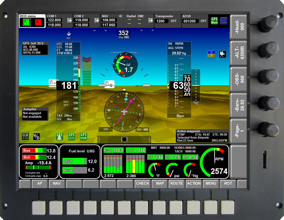
iEFIS CHALLENGER "Lite" (264mm 10"4 diagonal, XGA 1024 x 768 pixels) ships since August 2013.
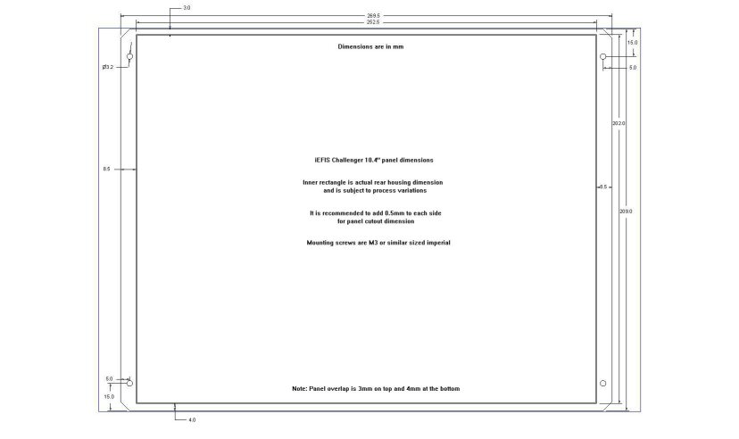
Dimensions : 270mm x 209mm, panel cut 252.5 x 202.5mm Download drawing
Weight: 1350g approx.
Do you want to try an iEFIS? Its possible right now by downloading the simulation program (requires a PC running Windows NT, 2000, XP, VISTA, Windows7) which simulates the operation of the iEFIS.
The simulator allows you to almost fully operate a virtual iEFIS. Perfect for learning how to use it without using a physical instrument, at home or at your club!
"iEFIS simulator"" : Download installation program iEFISG3Simulator.exe
Return to general description
|
MGL Avionic Glass Cockpit Stratomaster iEFIS Challenger

 Click on pictures to enlarge them.
Caution : dimensions of images on your computer screen depend on its resolution and may differ from actual iEFIS sceen dimensions.
iEFIS CHALLENGER (264mm 10"4 diagonal, XGA 1024 x 768 pixels) ships since August 2013.
Dimensions : 270mm x 209mm, panel cut 252.5 x 202.5mm Download drawing
Weight: 1300g approx.
Do you want to try an iEFIS? Its possible right now by downloading the simulation program (requires a PC running Windows NT, 2000, XP, VISTA, Windows7) which simulates the operation of the iEFIS.
The simulator allows you to almost fully operate a virtual iEFIS. Perfect for learning how to use it without using a physical instrument, at home or at your club!
"iEFIS simulator"" : Download installation program iEFISG3Simulator.exe
Return to general description
|
MGL Avionic Glass Cockpit iEFIS
iEFIS (R) (registered trademark)
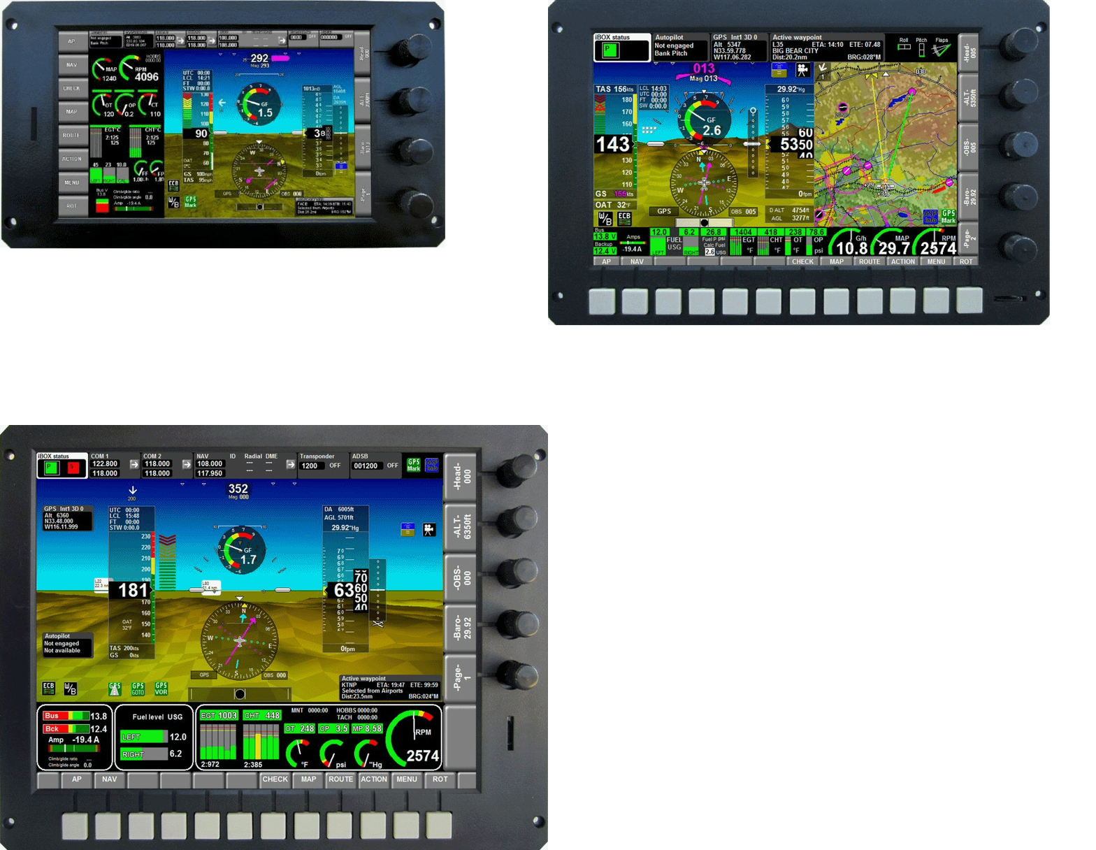
 Click on pictures to enlarge them.
MGL Avionics
iEFIS project
What is iEFIS ?
iEFIS is a
registered trademark owned by MGL Avionics. iEFIS is the next generation
EFIS system utilizing a custom developed, pressure sensitive, sunlight
readable touch screen that can also be operated using gloves. iEFIS
combines the undeniable advantages of simplyfied operation that a touch
screen can offer with rich traditional controls which are equaly
indispensible in the cockpit environment. The pressure sensitive touch
screen operates much like a tactile button does preventing false
activation when touching the screen during turbulent conditions. A simple
but highly effective solution...
What does the iEFIS architecture look like
?
iEFIS is highly modular in order to increase flexibility for special applications but also to reduce system cost for typical use.
Three panel sizes will be released initially. The panels contain powerful processing capabilities, high resolution, sunlight readable touch screens and traditional user interfaces but completely lack everything that makes an EFIS a "EFIS". There are no device interfaces, no sensors. This makes the cost of the panels very attractive. The actual EFIS part containing a rich multitude of interfaces, pressure sensors etc is contained in a seperate small unit that can be mounted behind the panel in a convenient location. This unit is called the "iBOX". If redundancy is needed, two of these can be used in a system in a controlled main and hot standby system.
Each iBOX connects via a private network to up to 8 iEFIS panels (which can be of various types). This makes multi-panel systems very affordable while at the same time greatly simplifying installation requirements.
Typical aircraft systems devices such as engine
monitoring systems (RDAC), AHRS, compass, external navigation and COM
systems all connect to the iBOX. The only wiring to a panel required is
power and the communications cable to the iBOX.
What are the iEFIS panel sizes
?
The first release is the 8.5" wide screen format
iEFIS Explorer shown in the image above. This will be
followed soon therafter with a 7" unit called the iEFIS
Discovery and the iEFIS Challenger which weighs
in at a large 10.4". The 7" explorer uses a special IPS technology screen
giving 180 degrees viewing angle in any direction which allows this device
to be used in either landscape or portrait mode as needed.
Does iEFIS preserve the flexibility of the
current MGL EFIS systems for user modification such as custom screen
designes ?
Yes, this is preserved - however more "plug and
play" choices are available to ease use by customers who do not want to
customize their units.
What about wireless ? What about my iPAD ? What
about my Android tablet ?
The iEFIS architecture offers a
wireless Wifi node that can take the place of any of the theoretical 8
panels you could connect to an iBOX. While this is primarily intended for
flight planning (such as upload your flightplan from a tablet) and flight
data recording (useful for experiments and aircraft manufacturers) - the
wireless node has access to everything a normal panel has so it could
become a full EFIS as well, just wireless. It is also possible to consider
using just an iBOX without any iEFIS panels at all and a iPAD or Android
"EFIS" perhaps for very low cost installations in smaller aircraft.
Unspecified availibility date.
I am a Android or iPAD developer. I want to make
an App for iEFIS.
You are welcome. The protocol required
to access the iBOX and iEFIS panels via the Wifi node shall be released to
the public domain. If you can send and receive data over a TCP/IP link you
are all set to go...
I want to write my own iEFIS software to run on
the iEFIS panels.
You have come to the right place. This
will be supported sometime in the future after the G3 upgrade of our
processing platform is expected (plug in upgrade PCB). This system runs a
basic version of Linux allowing you to do anything you like with the
panels...
When will iEFIS be available for ordering
?
iEFIS EXPLORER (8"5) ships since July 2012.
iEFIS CHALLENGER (10"4) ships since August 2013.
iEFIS DISCOVERY Lite (7") ships since october 20th 2014.
How does iEFIS affect the MGL EFIS
systems ? Are these going to die ?
No, not at all. These systems are in wide spread use and have a different architecture to the iEFIS panels and follow more traditional ways of thinking. These panels will not only continue to be supported but in fact will continue to be developed up to the G3 standard later.
Can I have dimensions for the panels - I want to see if they are going to fit.
Panel dimensions iEFIS
Discovery (7")
Panel dimensions iEFIS
Explorer (8.5")
Panel dimensions
iEFIS Challenger (10.4")
Subscribe to our MGL information list
Request catalog/prices 
Return to general description
|
iEFIS Architecture
|
iEFIS system
Architecture
The iEFIS is a modular system with the iBox at its heart. All system devices communicate with the iEFIS through the iBox via a robust 2-wire CAN Bus network. The iEFIS screens (up to 8 of any size) communicate with the iBox via the EFIS LAN through an RG-174 coax cable. External devices such as radios, transponders, etc., communicate with the system via the RS-232 and ARINC inputs on the iBox.
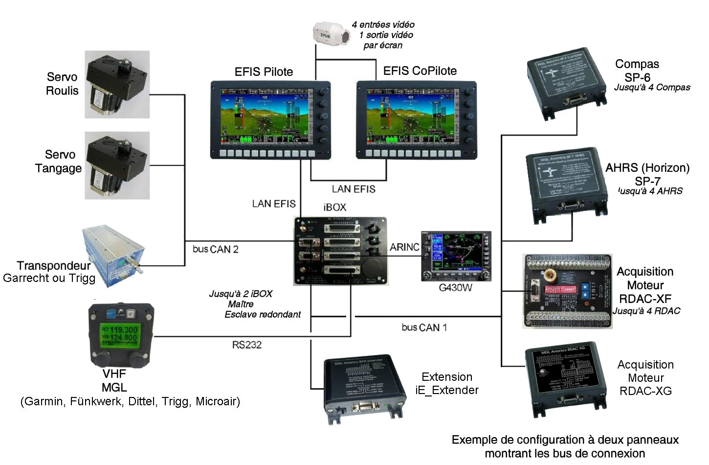 |
iEFIS System Modules :
Up to 8 iEFIS panels may be connected in a single system (1 required)
iBOX V1: Full featured, central interface for the iEFIS system (1 or 2 units)
SP-6 CAN: Compass/Magnetometer (up to 2 units)
SP-7 CAN: Attitude Sensor (up to 4 units)
SP-10 CAN: Flap, trim and gear controller (up to 6 units, up to 2 functions/unit, 6 functions max)
RDAC XF: Engine monitoring interface (up to 4 units/engines)
RDAC CAN: Rotax 912iS ECU interface (up to 2 units/engines)
MGL V6: COM radio (including full remote control)
MGL V10: COM radio (including full remote control)
MGL ECB system (up to 4 units, 48 breakers)
MGL iEFIS wireless node (one per system - not yet available)
MGL iEFIS wired node (up to 8 – including iEFIS panels)
MGL Autopilot servos (Bank, Pitch, Yaw)
Compatible Third Party Devices:
Garmin SL40 COM radio
Fünkwerk ATR500 COM radio
Fünkwerk ATR833 COM radio
Microair M760 COM radio
Dittel KRT-2 COM radio
Garmin SL30 NAV/COM radio
Garmin G430W and newer GPS/NAV/COM systems
Sandia Aerospace STX-165R Remote Mode-C transponder
Garrecht Mode-S transponder
Trig Avionics TT-21 & TT22 Mode-S transponder
Vertical Power VPX
Traffic systems compatible with ARINC 735 (TIS, TCAS, ADSB with TIS output)
Traffic systems: NavWorx ADS-B, FLARM, XRX PCAS
NavWorx ADS-B Transceiver for traffic/weather
Transponders Requiring Gray Code (Gillham) Encoded altitude
Older Analog Navigation Systems (CDI/LOC/GS) using +/-150mV differential outputs
External autopilots can be connected to NMEA (RS-232 port 6 on the iBOX) or ARINC steering signals.
|
Return to general description
|
| iEFIS "Lite" Architecture | |
|
iEFIS "Lite" Architecture
|
iEFIS "Lite" system
Architecture
Discovery "Lite" ships since october 20 2014.
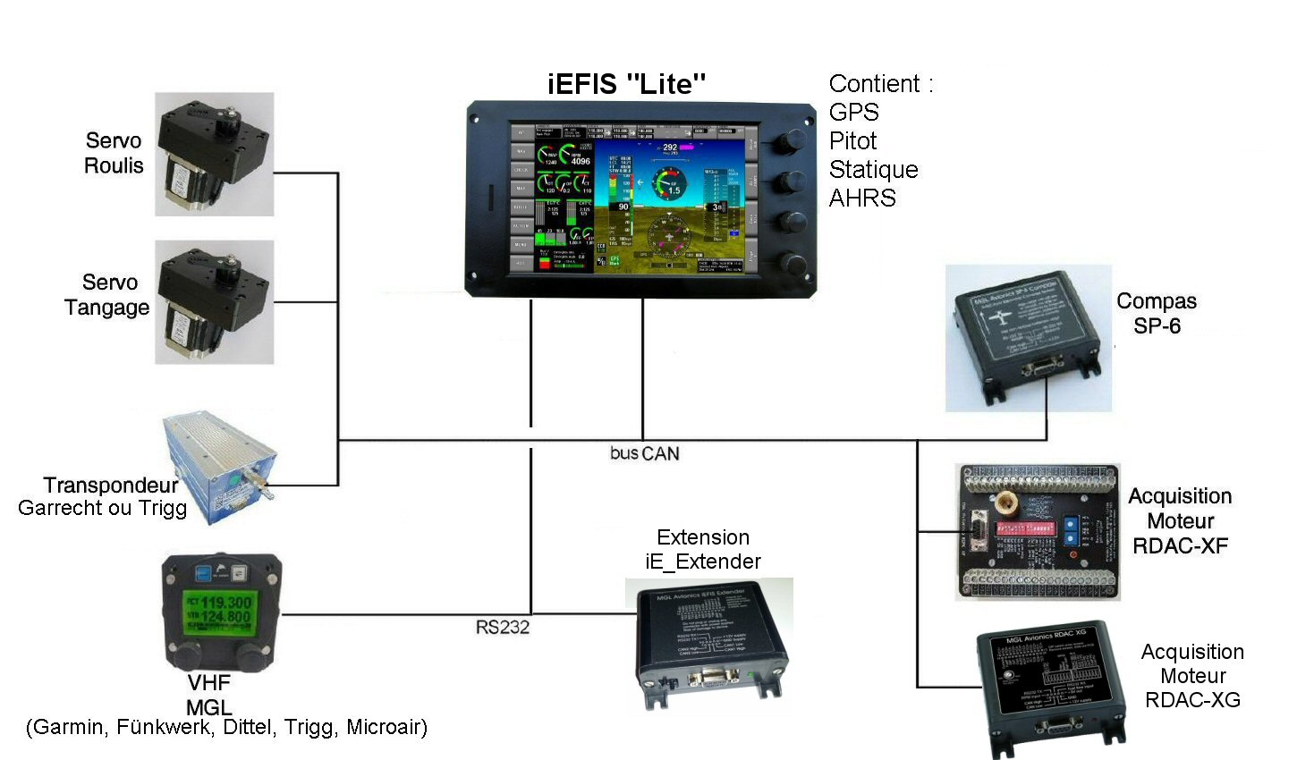
This version does not require the use of the iBOX and is thus suitable for applications where low cost and simplicity of the installation are required.
The “Lite” panel uses exactly the same firmware as a regular iEFIS system and is this not restricted in is capabilities, save for any function that requires specific hardware support by the iBOX.
The “Lite” panel itself includes altimeter and airspeed sensors, a built in WAAS GPS, AHRS, CAN interface for connection to any MGL CAN based peripheral as well as two RS232 ports for connection to items like radios etc. It is also possible to connect an EFIS extender module which provides additional analog and digital inputs and digital (switched) outputs, an AOA sensor as well as 5 RS232 ports for a total of 6 usable RS232 ports. It also provides an interface for a standard MGL OAT sensor (the Lite panel has a built in sensor intended mostly for open cockpit aircraft).
Up to two “Lite” panels can be used in a single system and they can share RS232 ports and CAN bus devices.
A typical comprehensive functionality “Lite” panel may consist of:
One or two EFIS panels
One RDAC for engine monitoring plus probes as needed
One SP-6 compass
Add to this:
One, two or three autopilot servos
SP-10 Flap and Trim controller
Also consider the large infrastructure of peripherals from MGL and third parties ranging from VHF radios, navigation radios, transponders, electronic circuit breakers and more.
 |
iEFIS "Lite" System Modules:
SP-6 CAN: Compass/Magnetometer (up to 2 units)
SP-7 CAN: External Attitude Sensor (up to 4 units)
SP-10 CAN: Flap, trim and gear controller (up to 6 units, up to 2 functions/unit, 6 functions max)
RDAC XF: Engine monitoring interface (up to 4 units/engines)
RDAC CAN: Rotax 912iS ECU interface (up to 2 units/engines)
MGL V6: COM radio (including full remote control)
MGL V10: COM radio (including full remote control)
MGL ECB system (up to 4 units, 48 breakers)
MG_Servo: Autopilot servos (Bank, Pitch, Yaw)
Compatible Third Party Devices:
Garmin SL40 COM radio (ou toute radio compatible SL40)
Garmin SL30 NAV/COM radio
Fünkwerk ATR500 COM radio
Fünkwerk ATR833 COM radio
Microair M760 COM radio
Dittel KRT-2 COM radio
Garrecht Mode-S transponder VT-01R (with MGL198 interface)
Trig TT21 & TT22 Mode-S transponder(with MGL238 interface)
Sandia Aerospace STX-165R Remote Mode-C transponder
Vertical Power VPX
Systèmes Trafic : NavWorx ADS-B, FLARM, XRX PCAS
NavWorx ADS-B Transceiver pour Trafic/Météo
External autopilots can be connected to NMEA (RS-232 port 2).
|
Please view the iEFIS “Lite” user and installation manual for details on the “Lite” functionality as well as differences to a regular iEFIS system.
Return to general description
|
| iEFIS "MX-1" Architecture | |
|
iEFIS "MX-1" Architecture
|
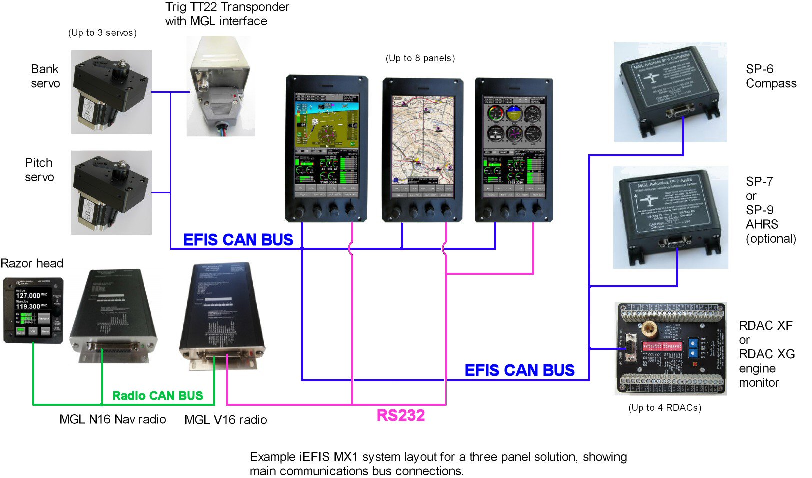
iEFIS "MX-1" system
Architecture
The iEFIS "MX-1" ships since august 2019.
This version does not require the use of the iBOX and is thus suitable for applications where low cost and simplicity of the installation are required.
The “MX-1” panel uses similar firmware as a regular iEFIS system. It does have partial synthetic vision. Effectively much the same as regular or "Lite" iEFIS, but no Terrain. You do have 3D runways, they are just drawn simpler as the CPU is not fast enough to do texture rendering. The MX-1 is not restricted in is capabilities, save for Terrain, 3D rendering and any function that requires specific hardware support by the iBOX.
The “Lite” panel itself includes two sets of altimeter and airspeed sensors, AOA sensors, a built in WAAS GPS, AHRS, CAN (FD) interface for connection to any MGL CAN based peripheral as well as four RS232 ports for connection to items like radios etc. It is also possible to connect one or two EFIS extender module(s) which provides additional analog and digital inputs and digital (switched) outputs, as 5 RS232 ports for a total of 6 usable RS232 ports. It also provides an interface for a standard MGL OAT sensor.
Up to eight “MX-1” panels can be used in a single system and they can share RS232 ports and CAN bus devices.
A typical comprehensive functionality “MX-1” panel may consist of:
One to three iEFIS MX-1 panels
One RDAC for engine monitoring plus probes as needed
One SP-6 compass
Add to this:
One, two or three autopilot servos
SP-10 Flap and Trim controller
Also consider the large infrastructure of peripherals from MGL and third parties ranging from VHF radios, navigation radios, transponders, electronic circuit breakers and more.
 |
iEFIS "Lite" System Modules:
SP-6 CAN: Compass/Magnetometer (up to 2 units)
SP-7 CAN: External Attitude Sensor (up to 4 units)
SP-10 CAN: Flap, trim and gear controller (up to 6 units, up to 2 functions/unit, 6 functions max)
RDAC XF: Engine monitoring interface (up to 4 units/engines)
RDAC CAN: Rotax 912iS ECU interface (up to 2 units/engines)
MGL V6: COM radio (including full remote control)
MGL V10: COM radio (including full remote control)
MGL ECB system (up to 4 units, 48 breakers)
MG_Servo: Autopilot servos (Bank, Pitch, Yaw)
Compatible Third Party Devices:
Garmin SL40 COM radio (ou toute radio compatible SL40)
Garmin SL30 NAV/COM radio
Fünkwerk ATR500 COM radio
Fünkwerk ATR833 COM radio
Microair M760 COM radio
Dittel KRT-2 COM radio
Garrecht Mode-S transponder VT-01R (with MGL198 interface)
Trig TT21 & TT22 Mode-S transponder(with MGL238 interface)
Sandia Aerospace STX-165R Remote Mode-C transponder
Vertical Power VPX
Systèmes Trafic : NavWorx ADS-B, FLARM, XRX PCAS
NavWorx ADS-B Transceiver pour Trafic/Météo
External autopilots can be connected to NMEA (RS-232 port 2).
|
Please view the iEFIS “MX-1” installation manual for details on the “MX-1” functionality as well as differences to a regular or "Lite" iEFIS system.
Please view the iEFIS “MX-1” user manual for details on the “MX-1” functionality as well as differences to a regular or "Lite" iEFIS system.
Return to general description
|
Stratomaster MGL iEFIS Différences
Differences between iEFIS, iEFIS "Lite" and iEFIS "MX-1"
The following table points out the differences between iEFIS, iEFIS "Lite" and iEFIS "MX-1"
| | | |
| iEFIS | iEFIS "Lite" | iEFIS "MX-1" |
|---|
| iBOX | Required | Not available | Not available |
| AHRS | Requires external SP-7 or SP-9 module(s) | Internal. Connection of 1 to 4 external SP-7 or SP-9 AHRS module(s)via CAN bus is possible | Internal. Connection of 1 to 4 external SP-7 or SP-9 AHRS module(s)via CAN bus is possible |
| ARINC | 3 x Rx, 1 x Tx | Not available | Not available |
| Analog navigation support for older NAV systems | 4 x balanced inputs | Not available | Not available |
| Gillman code transponder encoder interface | Yes | Not available | Not available |
| Analog inputs | 8 | 8, see *1) | 16 (2 x 8), see *3) |
| Digital inputs | 8 | 8, see *1) | 16 (2 x 8), see *3) |
| Digital outputs | 4 + 1 alarm | 4 + 1 alarm, see *1) | 10 (2 x 5), see *3) |
| RS232 ports | 6 | 2 + 4, see *2) | 4 + 4, see *2) |
| CAN bus | 2 | 1 | 1 (CAN "FD") |
| Airspeed range | Up to 600mph (at sea level) with Hi-Speed iBOX | Up to 280mph (at sea level) | Up to 280mph (at sea level) with Low speed sensor, Up to 600mph (at sea level) with Hi-Speed sensor |
| Altimeter range | up to 40.000ft | Up to 35.000ft | Up to 35.000ft |
| AOA | Yes | see *1) | Yes |
| OAT | Yes | Internal. External, see *1) | Yes |
| Two power inputs | Yes | No | No |
| Wifi link to external applications | Yes (requires Wifi interface module) | Yes (requires Wifi interface module) | Yes (requires Wifi interface module) |
| Video inputs | 4 x PAL/NTSC | None | None |
| Video output | 1 x VGA | None | None |
| Redundancy | Full, comprehensive | Partial | Partial |
| Terrain | Yes | Yes | No |
| 3D Synthetic vision | Yes | Yes | Partial |
*1) Requires optional iEFIS extender module
*2) Optional iEFIS extender module provides 5 RS232 ports for a total of 6 usable ports
*3) Up to two optional iEFIS extender modules (on CAN and RS232 Port4)
Return to general description
|
iBox
|
iBox
The Heart of the iEFIS
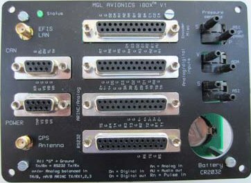
The iBox is the heart of the iEFIS system, and the conductor in the symphony of communication between all system devices and the iEFIS screens. The iBox contains the GPS engine (with antenna connection), the pitot/static sensors and Angle of Attack sensors. The iBox is the hub of communication for all the system devices (AHRS, RDAC, Autopilot Servos) and is also the hub of communication with all third party devices (radios, transponders, ADS-B, VP-X) via its RS-232 and ARINC interfaces.
 One iBox is necessary in every iEFIS system, and in cases where maximum redundancy is required, a 2nd iBox can be added to the system. The 2nd iBox acts as a ‘hot standby’ and is ready to take over all iBox tasks automatically when necessary, or on command by the pilot.
Click on the DB-25 connectors above to see more information on those connectors.
The Power Connector (pigtail harness included with every iBox):
The iBox can be powered by 1 or 2 Power Sources (as in the case of a backup battery system). It also has a Keep Alive Power input that maintains date and time and some non-volatile memory items without using the CR2032 battery, which can result in up to 10 years of life on the CR2032 eliminating the need to change this battery every year. The Outside Air Temp sensor also connects to the Power connector.
CAN connector (pigtail harness included with every iBox) :
The iBox features 2 CAN buses (CAN 1 and CAN 2). The system devices can be split up in any way on each of the CAN buses.
OAT probe
Our aluminum OAT probe is included with every iBox.
GPS antenna
Our tuned GPS Antenna is included with every iBox (inside mount)
iEFIS LAN coax
An RG-174 EFIS LAN coax cable is included with each system
|
|
Download the manual (French)
Download the manual (English)
Return to general description
|
iEFIS EMS
|
Surveillance Moteur (Engine Monitoring System EMS)
Engine monitoring
The iEFIS offers comprehensive engine monitoring for any engine. All engine data is captured via our RDAC (Remote Data Acquisition Computer) that mounts near the engine (in front of or behind the firewall). This data acquisition computer then sends all sender data to the iBox via the CAN Bus Network. No wiring harness for engine senders required!

The iEFIS can support up to 4 RDACs. Each RDAC could be used for a different engine, or in cases where additional inputs are required (such as monitoring a 9-cylinder radial, or a non-standard application), additional RDACs can be used to expand the monitoring on a single engine.
There are several RDAC options for the iEFIS system:
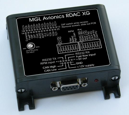
- RDAC XG - All engine functions with 8-channels for thermocouples
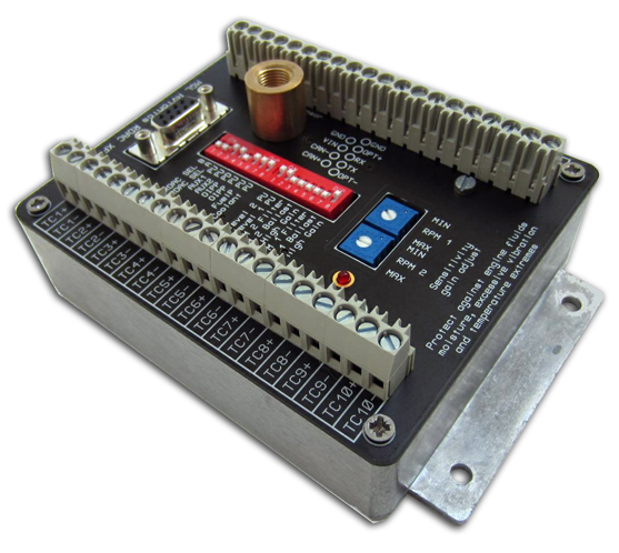
- RDAC XF MAP - All engine functions with 12-channels for thermocouples and manifold pressure (MAP)
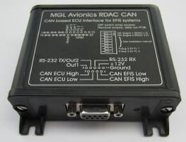
- RDAC CAN 912iS - Monitoring of the Rotax 912iS Engine directly from the ECU via CAN (up to 2 of these can be used)
- RDAC CAN MWB22 - Monitoring of the MW B22 Engine directly from the ECU via CAN
- RDAC CAN ULP - Monitoring of a UL POWER Engine directly from the ECU via CAN (up to 2 of these can be used) or via RS232
|
|
|
|
|
RDAC XG (8 canaux thermocouple)
RDAC XG
|
RDAC XF (12 thermocouple channels)
RDAC XF MAP
|
RDAC CAN 912iS for Rotax 912iS engine
|
|
Engine functions from RDAC XF:
- RPM x 2
- Hobbs Time
- Tach Time
- Maintenance Timers
- EGT (up to 12 total EGT/CHT)
- CHT (up to 12 total EGT/CHT)
- Oil Temperature
- Oil Pressure
- Fuel Pressure
- Water Temp (if required)
- Carb Temp (if required)
- Fuel level x 2 (with resistive or voltage senders)
- Fuel flow x 2 (using fuel flow sensor or fuel injector signal)
- Current sensor input
- Manifold Pressure
EGT Lean Assist:
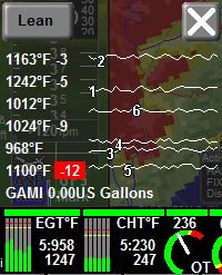
Just press on the EGT bargraph display on the touchscreen at any time and automatic peak detection will be enabled. A graph will begin generating making it easy to spot the first EGT to peak and it will then display lean or rich of peak differential.
Alarms:
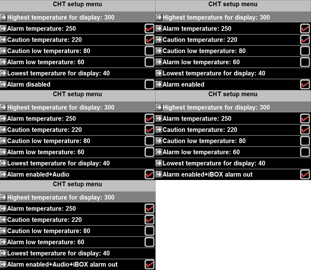 Whenever any engine parameter is exceeded an alarm will be initiated. The alarm can be setup to be any or all of the following (see the alarm options in the CHT menu at right for all options available in each sender set):
- On screen warning
- iBox Alarm Out External contact (panel master caution light or buzzer)
- Audio voice alert
Manuals :
Installation manual RDAC-XF (PDF)
Sensor installation on Lycoming engine (PDF)
Installation manual RDAC-CAN 912iS (PDF)
|
Return to general description
|
iEFIS AHRS
|
 Attitude/Heading Reference System (AHRS) Attitude/Heading Reference System (AHRS)
AHRS
The latest MGL Avionics SP-6 CAN and SP-7 CAN AHRS sensors can be used with the iEFIS. They connect to the iBox via the CAN Bus. You can use up to 2 SP-6 Compass sensors and 4 SP-7 Attitude sensors with each iEFIS system if redundancy is required. The iBox gets information from all sensors and uses the best data it has to come up with an attitude/heading solution.
Made by MGL Avionics, these are some of the smallest aviation AHRS sensors available today.
|
SP-6 CAN Magnetometer (Compass sensor)
|
SP-7 CAN Attitude (horizon) sensor
|
|
What is it?
The SP-6 CAN is a magnetic compass sensor (magnetometer) for use with all MGL Avionics products that show heading. It contains a three axis magnetic field sensor and a 3 axis accelerometer. The system uses a Cortex M3 32 bit processor. If an SP-7 CAN AHRS is used on the same communications link, tilt compensation can be performed using gyro based attitude data.
What information can be displayed on the EFIS?
Magnetic Heading
Wind speed and direction vector
Technical
Dimensions:Approx 3.5” x 3.5”
Weight: 175g with connector (6 oz)
Power consumption: 50mA; 120mA (chauffage en route)
|
What is it?
The SP-7 CAN AHRS is MGL Avionics's seventh generation AHRS system (attitude sensor) for use with all MGL Avionics products that display attitude. The core building blocks of the system include a three axis ST MEMS rate gyroscope, a three axis ST MEMS accelerometer and an ARM Cortex 32-bit microprocessor system. The SP-7 CAN will allow the display of attitude (horizon), G-force, turn rate, and slip/skid on MGL Avionics products that allow these features.
What information can be displayed on the EFIS?
Attitude
Slip and skid
G-Force
Technical:
Dimensions: Approx 3.5” x 3.5”
Weight: 175g with connector (6 oz)
Power cinsumption: 50mA; 120mA (heater on)
Degrees per second: 250 deg/sec typical
|
|
Manuel :
SP-6 and SP-7 User and Installation Manual (PDF)
|
Return to general description
|
Built-In Autopilot
|
Servos for you MGL iEFIS Avionics
Built-In Autopilot
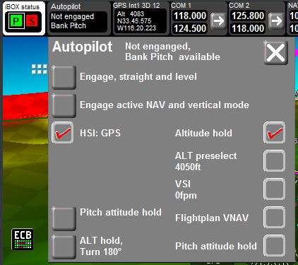 The MGL Avionics iEFIS contains a built-in autopilot. All you do is install our servos in the aircraft and the control and AP engage/disengage is handled directly by the iEFIS using the keypad, or via a remote switch. No other control modules are required.
The Servos connect to the iBox via the CAN Bus network like all other system devices.
The iEFIS handles all autopilot controls so that once you have engaged it, it will couple with any navigation source you select from that point on seamlessly. There is no need to change modes.
You can press on the Autopilot control on the touchscreen and then select the first Engage option for straight and level flight. This will sync altitude and heading bugs and maintain course and altitude. If if you then select a GPS Goto, it will switch over to the new Navigation mode automatically.
If you select the 2nd Engage mode (Active Nav and Vertical Mode) it will use the selected lateral and vertical modes you have preset:
-
When you engage HSI for lateral steering, it will follow the active HSI selection.
-
There are 5 Vertical modes to choose from, including Altitude Hold, Altitude Preselect, VSI Hold, Flightplan Vertical Nav, and Pitch attitude hold.
There is also an emergency ALT Hold, 180 degree turnback to get you out of trouble if you accidentally lose visual reference when flying near weather.
MGL Avionics servomotors
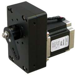 Our Servos are fast, accurate and high-powered:
The MGL Avionics Servo feature include:
- Precision machined and anodized solid Aluminum housing
- Output shaft runs inside double bearings
- 12 bit output shaft position measurement (sub 0.1 degree resolution)
- Zero contact magnetic output shaft position measurement (no “pots”)
- Force measurement (no additional external subsystems required)
- Automatic slip detection
- Digitally adjustable maxim torque setting
- Robust sub D9 connector simplifying inspection and modular installation
- CAN and RS232 interfaces
- Wide input voltage range (8V – 30V)
- Output arm equipped with safety sheer screw
- 4 + 4 mounting holes to simplify installation (4 side mounting holes)
- 8 holes to fit travel limiting bolts/plate (preventing “over center” lock-up)
- Diagnostic LED indicating communication mode and errors conditions
- 360 degree freedom of movement to simplify installation and setup
- Maximum holding torque: 4.8Nm
- Low residual torque: 0.28Nm
- Weight : 1380g approx.
- Dimensions : 36 x 63.5 x 101.6mm approx. Top view Side view
|
|
Download servomotor manual (English): MGL_Servo.pdf
Download "Autopilot" maniual (English): autopilot.pdf
Return to general description
|
iEFIS Touch Screen
|
The Big Difference...
Touch Screen
The iEFIS features a Resistive Touchscreen with all glass components (no plastic overlays). The touchscreen can use used with gloves and actually requires a ‘Push’ to activate a function. This prevents accidental touches, and allows you to secure your finger on the screen in the correct location before ‘pressing the button’. You can actually rub your fingers all over the screen gently and no functions will activate. This is a touchscreen made for use in aviation and in turbulence.
Retains Push Buttons and Rotary Knobs
There is also a row of buttons beneath the touchscreen (Explorer and Challenger) that can activate all functions without touching the screen if you prefer this control method, and a row of multifunction rotary knobs along the side.
 Instant Access
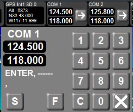
The real value in the touchscreen lies in being able to access a function just by reaching out and touching it. You don’t need to activate a menu and then scroll down with a knob and then select your function. You just touch it. If you want to find info on an airport on the map, just touch it. If you want to set the frequency on the radio, just touch the radio display and a numerical keypad will pop up.
Onscreen Quick Access
Want to adjust the altimeter? Just touch the altimeter display.
Want to lean your mixture with EGT? Just touch on the EGT bargraph.
Want to change your navigation source? Just touch on the HSI.
Full Keyboard
If you need to enter any alphanumeric characters, a full QWERTY keyboad will pop up.
You see it - you touch it. No scrolling down lists or drilling deep into menus.
|
Return to general description
|
iEFIS Moving Map GPS
|
Moving Map GPS Navigator
NAVIGATOR
 The iEFIS features a 50-channel WAAS-capable GPS receiver (with RAIM), with a host of moving map navigation features. All GPS databases are from freely available sources, and are editable by the user where applicable. Jeppesen NavData is also available worldwide as a subscription service, as well as PocketFMS (Use Desktop edition of PFMS to be able to select FIR's, as the world database can be too large).


Get Navidata updates here
The following map layers are available for display on the iEFIS:
-
Airports/Navaids/Airspace/Obstacles database
From free sources (such as the FAA) or from Jeppesen/PocketFMS. Includes runway information and frequency information and obstacles. Entire world available.
-
Terrain
In GTOPO format - freely available. Worldwide Available.
-
World Vector Basemap
Major roads, rivers, borders, cities and towns for the entire world.
-
Raster
Any scanned image (or digital Sectional file) can be used after processing with the free MGL Map Maker software. Please note that the user must respect Copyright and Intellectual Property laws.
We can supply (for EFIS purchased from Delta Omega) iEFIS compatible raster maps from AirMillion (Carribean, France, France WeekEnd, Iberia, Germany, Italy, Greece & North Balkans, Greece & South Balkans, UK, UK (500k), Eastern Europe). These files are associated to one or several iEFIS serial number(s) and can be used only on iEFIS having the proper serial number.
Please contact us for a quote.
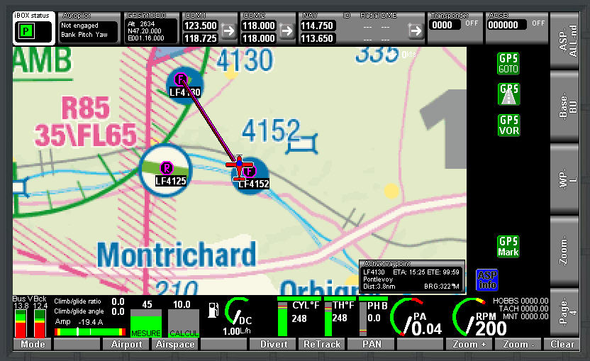
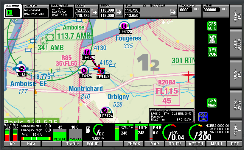
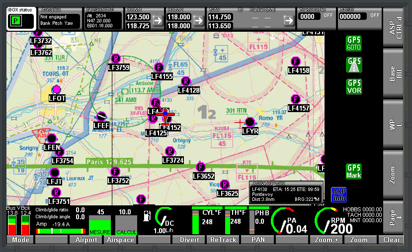
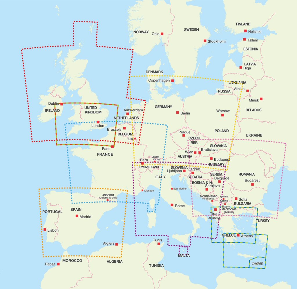

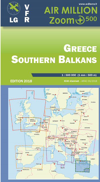
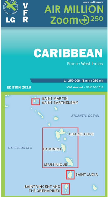
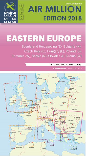







All of these layers (including the AirMillion raster map of country of delivery, if available) are shipped installed with each EFIS delivered by Delta Omega.
Major Functions:
NAV Softkey Function brings up various options including the Nearest Airport function. From these menus you can find airport information, runways, frequencies and then Goto an Airport/Navaid/Fix.
A full Alphanumeric Keyboard pops up for Searches (thanks to the Touchscreen!):
Route Function allows you to activate routes from the SD card (created in our Flight Planner software or by Seattle Avionics Voyager) or create routes directly in the iEFIS. Routes can be built just by touching airports on the screen - easy as pie!
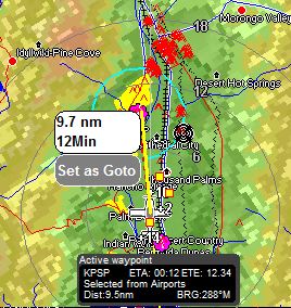
The touchscreen brings flight planning to life! Click any airport or point on the map and you can instantly see how far it is away from your current location and time to waypoint. One more click and you can Goto that waypoint.
|
Return to general description
|
iEFIS HITS and 3D
|
Highway in the Sky
HITS and 3D Synthetic View
The iEFIS features ‘floating box’ Highway-in-the-Sky (HITS) navigation as well as providing the user with a 3D depiction of the outside world for situational and terrain awareness.
This 3D View shows you the elevation of terrain that is at your altitude and above...
It shows you obstacles on the moving map and on the 3D View, so that you don’t run into anything when flying near terrain. And it draws a flag above airports ahead of you with Time and Distance to airport, like street signs on a freeway:
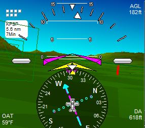
It shows 3D runways, with thresholds labeled so you know you are approaching the airport as planned:
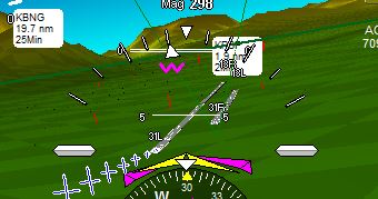 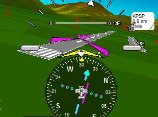
Runway Awareness at Long Beach Airport (KLGB):
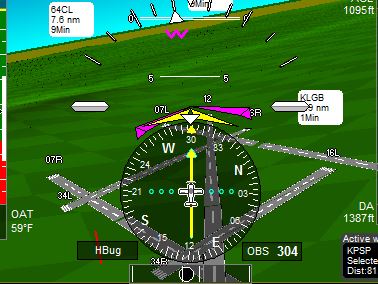
EFIS 3D View Display Options Available:
:
Checkerboard:
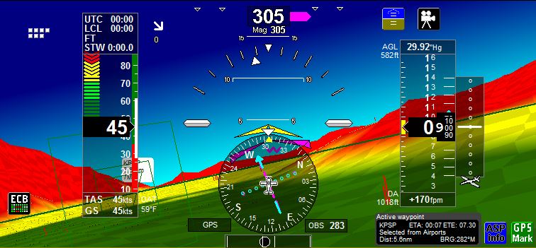
Modulated:
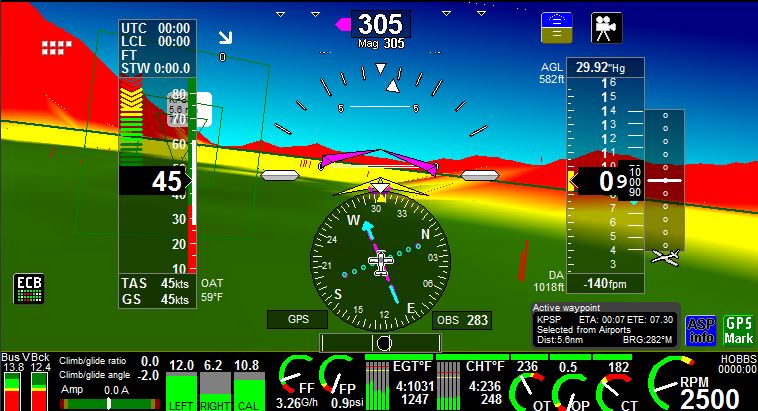
Textured:
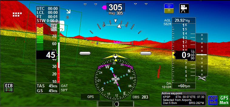
|
Return to general description
|
iEFIS Alarms
|
Voice Alerts and Copilot Mode
“Airspace Ahead!”
 The iEFIS has a built-in voice alert system. Un logiciel utilitaire vous permet, si vous le souhaitez, d'enregistrer vous-même les messages vocaux.
In the alarm setup you can choose the following alarm outputs for each item:
- On screen warning
- iBox Alarm Out External contact (panel master caution light or buzzer)
- Audio voice alert
The iEFIS will also give you airspace warnings, speed warnings, traffic warnings and any warnings setup by the user.
 
“Sixty-five!”
Mode Copilote
The iEFIS ‘Copilot Mode’ allows you to setup the EFIS to call out airspeeds whenever you get below a predetermined airspeed. You can select the time interval for these airspeed callouts.
Copilot Mode allows the pilot to keep his/her eyes outside the cockpit on landing and still keep a good awareness of airspeed.
65... 62... 60... 58... 57...
|
|
iEFIS GVOR and GLS
|
Radio Navigation and GVOR / GLS
HSI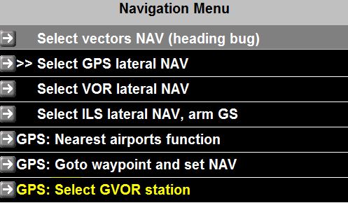
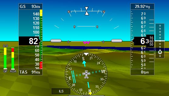
The iEFIS can interface with the Garmin SL30 Nav/Comm and display active and standby navigation on the screen with a VOR/Localizer/Glideslope indicator.
Alternatively, your MGL Avionics EFIS can ‘fake’ radio navigation using only its onboard GPS and its database of VOR stations. We call this GPS VOR (GVOR). For airports where we have the coordinates of both runway thresholds (most airports) we also draw a VFR glideslope (you set the glide angle an x-distance down the runway for touchdown). We call this GPS ILS (GLS) navigation.
GVOR
Using the NAV Softkey at any time you can view nearest GVOR stations. HSI will display GVOR radial to current position and will show GPS DME.
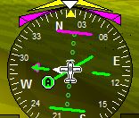 
GLS
Use the NAV Softkey to select Nearest Airports. Runways with a GLS approach available will be labeled ‘GLS’. Select the runway and the approach and then follow the green crosses to landing...
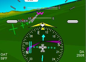 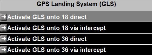
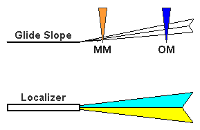
Localizer and Glideslope displayed on sample iEFIS Screen
(Outer Marker and Middle Marker sounds play through headset via iBox voice alerts)
|
Return to general description
|
iEFIS NAV/COM control
|
Radio Control
Set Frequency
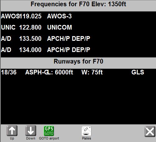 The iEFIS greatly reduces workload when flying in busy airspace environments by helping you find and set frequencies to your airband transceiver.
How does it work?
Firstly, you need a compatible radio with a serial input connected to your MGL Avionics iEFIS. Right now this includes:
- MGL V6 Com
- MGL V10 Com
- XCOM 760
- Garmin SL-40
- Garmin SL-30 nav/com
- Filser
- Fünkwerk
- Dittel KRT-2 (Note: The Dittel protocol does not insure 100% synchronization beetween VHF and EFIS)
- TRIG TY91
- Microair M760 Req Q (configured as “SL40” in iEFIS)
Then, simply call up the airport info page and then tap the frequency you want to set it straight to Active on your radio.
You can also flip-flop frequencies or enter them using the numerical keypad when necessary. MGL Avionics radios offer FULL remote control including all setup and volume control using the iEFIS rotary controls.
|
Return to general description
|
|
|
|
 |
 |
 |
 |
|
|