
|
 |
 |
 |
 |
|
|
|
MGL Avionic ODYSSEY VOYAGER EFIS "GENERATION 2"
Images on this page are created from screen captures using the Odyssey simulator.
The actual instrument uses a graphics processor capable of sub-pixel rendering that removes visual effects such as "jagged edges" on angled lines.
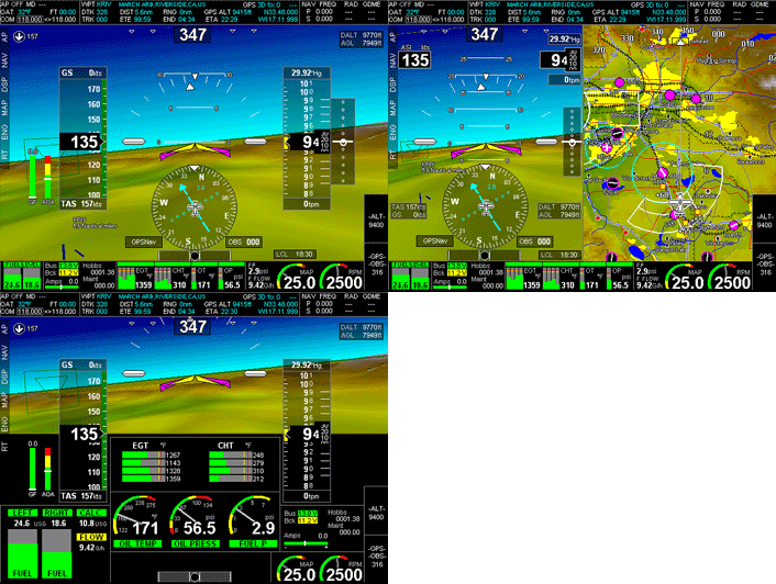
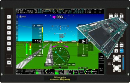 Click on images for a large version.
This product range is obsolete and replaced with the iEFIS range.
MGL Avionics has released the "Generation 2" upgrade for the popular Odyssey and Voyager EFIS systems.
All systems shipped are now in G2 status with unchanged pricing meaning even more EFIS for the money than before. Adding powerful new graphics hardware and doubling the processor speed means unmatched capability and value.
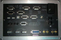
 See a drawing describing simple system architecture of ODYSSEY.
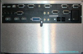
See a drawing describing global system architecture of ODYSSEY.
Inscrivez vous à notre liste d'information MGL
|
MGL Avionic ODYSSEY VOYAGER EFIS Fonctionnalités
10.4" Top quality, wide temperature range, direct sunlight viewable TFT screen with non-reflective surface etch. VGA resolution (640x480)
Robust, composite and aluminium housing with control rich user interface including user assignable buttons and rotary controls.
For panel dimensions and cutout information download this document: Odyssey panel cutout.pdf.
Light weight, 1.9Kg, simple mechanical installation, no brackets required.
Features listed here are only some of the available functionality, Odyssey, like its smaller brother Enigma, is a dynamic and very flexible development. Odyssey includes all of the Enigma functionality and adds items related mainly to its additional interfaces (ARINC429 etc).
Software based additions to functionality are made available to end users via free and unrestricted internet download with the actual task of updating a system being a simple and quick process taking only a few seconds.
Odyssey is fully compatible with the Enigma database system and application programs, all of which are available free of charge via internet download. Please note that 3rd party applications created by other companies or individuals may require purchase or licensing. Contact the relevant owners/creaters of these applications directly for information.
Load a schematic describing the ODYSSEY database generation process. (Click here for PDF format)
Pour être tenu au courant des évolutions, inscrivez-vous sur
notre liste d'information MGL
Primary flight system
Altimeter: -700 to over 40.000 ft range, 1ft resolution at sea level.
Airspeed: 16mph to 250mph (default) or 28 to 600mph ranges (optional).
Vertical speed: 2000 ft/min analog displays, 10.000 ft/min digital displays. TE mode available.
AOA: 18 degrees nominal range (Range set during calibration flight).
Compass : Supports optional compass modules SP-2
. The EFIS contains a complete precise model of earth's magnetic field, including magnetic variation with time (It is therefore not necessary to enter the local variation of your flight locatuion).
Attitude : Supports optional attitude modules SP-x
Navigation
Built in 16 channel WAAS GPS with RAIM, can use external GPS feed if required.
Connection to standard NAV radios for ILS, Glide slope, VOR: RS232 serial, ARINC 429, 150mV analog inputs.
GPS only simulation of VOR navigation and ILS, Glide slope.
GLS (GPS landing system) with highway in the sky 3D navigation to runway threshold.
HITS (Highway in the sky) navigation system for GPS waypoints and routes.
Long range 3D terrain lookahead with free World-wide terrain database (Synthetic vision, range to several 100 Km's containing up to 1 million square KM).
3D runways with live approach information without pilot interaction.
Moving map navigation using raster or vector maps with zoom levels extending to continent wide proportions.
Unrestricted ability for user to create and edit navigation data as well as raster and vector maps using free software applications.
Navigation data from free sources as well as subscription products from PocketFMS and Jeppesen Navdata (soon).
Garmin 400/500 series compatibility via ARINC (including the 430W).
User configurable "plates" database with plates viewer including geo-referenced plates.
Create 18 different types of holding patterns "on the fly". Holds made simple with just a few key presses...
Built in flight panning and route creation tool. Easily create route waypoints from any source...
Flight director coupled to autopilot (can be used without autopilot).
Traficc
Support for various types of traffic information systems:
TCAS, ARINC 735 compatible.
TIS from sources such as GTX330 and compatibe.
PCAS XRX via RS232.
FLARM via RS232.
Engine Monitoring
Single or dual engines, normally aspirated and turbine, fully flexible monitoring setup to cater for any type of engine.
Uses standard, low cost RDAC remote engine monitoring modules for ease of installation as well as J1939 (CAN bus) based engine monitoring.
EGT,CHT,Oil temp,Oil pressure,RPM,Coolant temp,fuel flow,fuel level(s),fuel pressure,voltage,current,... etc,etc.
Engine leaning assist with graphical display of EGT temperature curves.
Supports up to two Remote Data ACquisition modules
RDAC for dual engines or many measurement channels. Supports XB, XD et VD RDAC models.
Possibilité d'enregistrement sur carte SD des paramètres moteur (toutes les secondes).
Optional direct connection to engine ECUs via uCAN module. Reauires a specific study. Contact
support@delta-omega.com
to request a quotation
Built-in Automatic Pilot
Odyssey/Voyager includes an internal autopilot.
Using the optional COM extender module, Trio Avionics or PWM (Pulse Width Modulation) servos can be connected.
1,2,3 axis or more can be supported. (2 as if today)
The internal autopilot can be connected to any available navigation source, both internal or external.
External autopilots are supported via either NMEA interface or ARINC.
Flexibility
MGL's systems are known for their flexibility and the G2 editions of the Odyssey and Voyager build on this, however at the same time these systems now contain fixed operation options including built in screens and a selection of built in choices (type of aircraft, type of engine monitoring).
The previous flexibility allowing users to completely customise their displays however has been fully maintained for those that have special needs.
Other features
Velocity vector functionality.
Automatic flight folio flight logging with export to PC based flight log viewer program (Enigma Flight Planner). Logs up to 1000 flights with internal viewer.
"Black box" style logging of all flight data (primary flight, navigation, attitude, engine monitoring) to SD card with free PC based viewing application including export of flight path to Google Earth.
See Recording Setup.
Interface to COM and NAV radios for setting of frequencies from internal data base or rotary controls.
Interface to Vertical Power's VP-X electronic circuit breaker system.
9 fully user customisable screens using free Odyssey Screen Designer and simulator software.
Layout your screens exactly the way you need them.
Voice prompts and warnings (if connected to suitable audio system), engine monitoring, navigation, primary flight etc. Voice prompts can be recorded to requirements using free PC application.
Fully "Enigma" map and database compatible.
Operates as single panel, dual or triple panel system with full, unrestricted functionality in each panel.
Low power requirements, 1.5A at 12V at full backlight level.
Dual backlights with independent power supplies.
Connects to "I/O Extender"
for applications requiring large amount of additional monitoring and control such as remote control of Odyssey panel (using "hat switch" or similar on joystick).
Easy and fast software upgradability using SD card. Free updates for life, high frequency of update cycles.
Built in high capacity solid state hard drive (no moving parts, no G-force restrictions). All navigation data and maps may reside on internal drive.
Ability to operate fully from external SD card slot including external booting of system (emergency operation in case of hard drive failure or during system test and configuration).
User selectable units of operation, meters/feet, mph/knots/kmh, liters/galons etc
Connect the Odyssey simulator to Microsoft Flight Simulator to aid in your screen design and setups.
Connect a real Odyssey instrument to Microsoft Flight Simulator for pilot training.
Interfaces
RS232 port 2 - NMEA autopilot output, serial altitude encoder output / external GPS input
RS232 ports 1,3,4,5 (allocatable as required: NAV/COM radio, FLARM, XAON XRX traffic systems, XM Weather interface).
Ports 1 and 2 are standard fit, Ports 3,4,5 are available with optional USB RS232 port extender module.
ARINC429 - 1 x TX, 3 x RX. Normal and high speed. TX->Autopilot messages, RX->NAV radios, traffic information systems (ARINC 735).
USB Host - 2 x. Interconnect between multiple panels, MGL communications peripherals (Weather systems etc).
USB Device - 1 x.Interconnect between multiple panels (slave connection).
CAN (J1939). Automotive multidrop communications interface.
Analog - 4 x 150mV analog differential inputs for connection to older generation NAV receivers (ILS, Glide slope and flags).
Audio - high and low level outputs for audio voice prompts.
Airtalk - 2 x multidrop communications bus (MGL propriety bus). Used to connect MGL attitude and compass sensors.
Gillman altitude encoder output (standard parallel output bus).
Input for Rotor speed sensor (Rotor craft usage only).
GPS antenna input for active GPS antennas (SMA connector).
Alimentation
One input to 12V nominal supply. System operates from 6V to 28V.
One input/output for optional rechargeable backup battery (recomended sealed lead acid, 2-5A/H capacity). Built in current limited charger.
One secure 12V supply output for connection of vital equipment (AHRS, compass sensor, engine monitor(s)).
Start up time 4 seconds approx.
|
MGL Avionics EFIS "GENERATION 2" ECRANS STANDARD
Click on pictures to enlarge them
The following section shows some of the built in screens in action (based on the Odyssey simulator - a free download). You can use these screens as they are (or select from other available options), use these screens as bases for your own designes or start completely from scratch with a blank screen. These screens are also used on the Voyager (The Voyager is 100% compatible to the Odyssey).
The choice is yours...
Common to all screens (using the built in default screen designs):
Open and select a video channel and overlay the video on top of the screen. Size of the video image is determined by the screen itself (for example - on the map screen the video fills the entire area of the map, on other screens the image is smaller and positioned so to allow continued use of the indicators. Further "information" or "Info" pages can be opened in appropriate positions to show further text or graphical indicators as needed.
Ecran 1
Click on image to see a large version
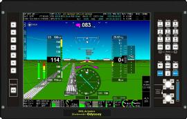
Typical 3D synthetic vision page showing approach to Los Angeles runway 07R. This screen has a small engine monitoring bar.
Ecran 1 avec HITS
Click on image to see a large version
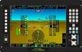
This screen shows typical use of the HITS (Highway in the sky) navigation.
Ecran 1, relief Terrain
Click on image to see a larger image

Approaching the coast. Shows off the terrain blending and use of gridlines to give a sense of distance and perspective.
Ecran 1, avec caméra FLIR
Click on image to see a large version
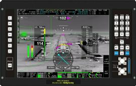
Here we have switched the 3D synthetic vision image to a forward looking infrared camera (FLIR) - staged image.
Ecran 2
Click on image to see a large version
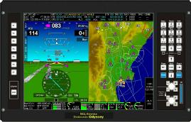
This shows a split screen between synthetic vision/primary flight and a vector map showing airspace boundaries and airports with cultural map items suppressed.
Ecran 3
Click on image to see a larger image
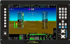
This shows a typical 3D synthetic vision screen but with a larger engine monitoring section.
Ecran 4
Click on image to see a larger image
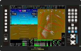
Split screen synthetic vision and vector map using larger area for engine monitoring.
Ecran 5
Click on image to see a larger image
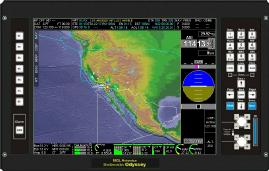
Screen dedicated to moving map navigation. Select from raster maps (georeferenced, scanned paper maps) or vector maps. Zoom levels extend to continent wide proportions.
A smaller area is dedicated to primary flight information, maximizing the space for maps.
Ecran 7
Click on image to see a larger image
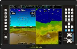
Another version of the split screen with engine monitoring removed
Ecran 9 avec plateaux d'approche
Click on image to see a larger image
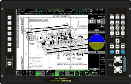
This screen allows navigating through plates in flight, preserving all important flight information displays at the same time.
Here a geo-referenced airport plate is shown (KLAX).
Plates
Click on image to see a larger image
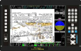
Similar to the previous screen, this version shows a typical approach plate.
Flight planning
Click on image to see a large version
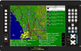
This image shows the built in flight planning tool.
Easily create routes from any source.
Create waypoints directly from map references, use the built in database or pick from other routes.
Holding pattern
Click on image to see a larger image
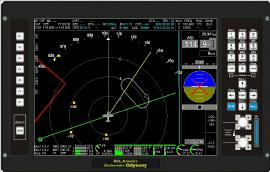
This image shows a map in "navigation mode" with an active holding pattern (entry fix marked with small triangle pointing in the required direction).
The hold changes size as your airspeed changes.
Also visible is a VOR radial and the current OBS
Engine leaning
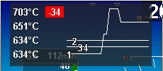
This image shows a quick simulator image of the engine leaning function for a 4 cylinder.
In the above image cylinder one EGT peaked first and is now 34 degrees below peak (and 2,3,4 did not change at all).
Activation requires a single button press and the image overlays in a translucent manner.
The graphic moves from right to left showing the last relevant movements of the EGT temperatures.
|
UPGRADE ODYSSEY VOYAGER EFIS "GENERATION 2"
This upgrade is not available anymore because G2 processors are unobtainable. They have been replaced with the G3 processors, which are used only on the "iEFIS" range.
We can not anymore upgrade your "Generation 1" Odyssey/Voyager EFIS to "Generation 2".
The Odyssey/Voyager G2 status introduces the new MGL168 processing hardware that also includes a dedicated graphics engine with support for video inputs and even a VGA output.
Four Vidéo inputs allow connection to video sources (day and/or thermal cameras).
A VGA video output to connect an optional external VGA screen.
The upgrade service is performed in our facilities
- Inspection à la réception et inventaire système
- Sauvegarde de la configuration sur CD
- Décapotage EFIS
- Retrait de la carte processeur MGL152 (qui vous sera retournée avec l'EFIS comme pièce détachée)
- Installation de la carte processeur MGL168B
- Modification pour montage de la carte de connexions video
- Installation de la carte de connexions video avec connecteurs DB
- Remontage de l'EFIS
- Mise à jour logiciel niveau G2 avec installation des écrans standard
- Test d'acceptance
- Emballage et mise à dispo pour expédition
Durée de l'OPération (DOP) (assumant que nous avons la carte MGL168B en stock, ce qui est à confirmer AVANT de nous expédier l'EFIS)
- DOP défini depuis l'arrivée en nos locaux jusqu'au "prêt à expédier"
- DOP Standard : Une à deux semaines.
- DOP Urgent : 2 à 3 jours. surfacturation de 30%. Disponibilité à confirmer AVANT de nous expédier l'EFIS.
Inscrivez vous à notre liste d'information MGL
|
|
|
|
 |
 |
 |
 |
|
|