
|
 |
 |
 |
 |
|
|
|
|
iEFIS EXTENDER

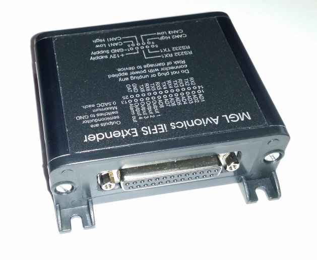
Extension module for iEFIS "Lite" or standard iEFIS.
The iEFIS Extender is used mainly to add additional capabilities to an iEFIS "Lite" system.
It can also be used with regular iEFIS systems where it will provide additional analog/digital inputs and digital outputs.
On iEFIS "Lite" system it connects to one or two iEFIS “Lite” panels using panel RS232 port 2 which is used in a special high speed mode.
CAN bus 1 and CAN bus 2 are not used.
It provides:
- Pressure senders for AOA (Angle Of Attack) indication
- 5 RS232 serial ports (for a total of 6 usable ports on the "Lite")
- 8 Analog/Digital inputs. These are the exact equivalent of the 8 analog/digital ports on an iBOX used with a regular iEFIS system.
- 5 Digital outputs (open collector, 0.5A). These are the exact equivalent
of the 5 outputs on an iBOX used with a regular iEFIS system.
- 1 OAT sensor input compatible with a MGL OAT sensor (LM335 semiconductor
sensor).
On the regular iEFIS system it connects using CAN bus interface 1.
RS232 ports, CAN bus 2, OAT sensor and AOA sensor are not used.
It provides:
- an additional 8 Analog/Digital inputs to the iBOX for a total of 16.
- an additional 5 Digital outputs (open collector, 0.5A) to the iBOX for a total of 10.
Interfaces :
- 2 CAN interfaces
- 1 serial interface
Weight: 140g approx. (without connectors)
Dimensions : 90 x 70 x 31mm approx.
Ref : MG_iE_Extend Extension module for iEFIS "Lite"
Ask for a Catalog/Price list
Download iExtender manual(French): iE_Extender_FR_w.pdf
Download iExtender manual(English): iE_Extender.pdf
Top of page
|
| ECB Electronic Circuit Breaker | |
|
|
Electronic Circuit Breaker
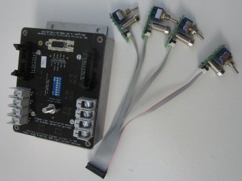
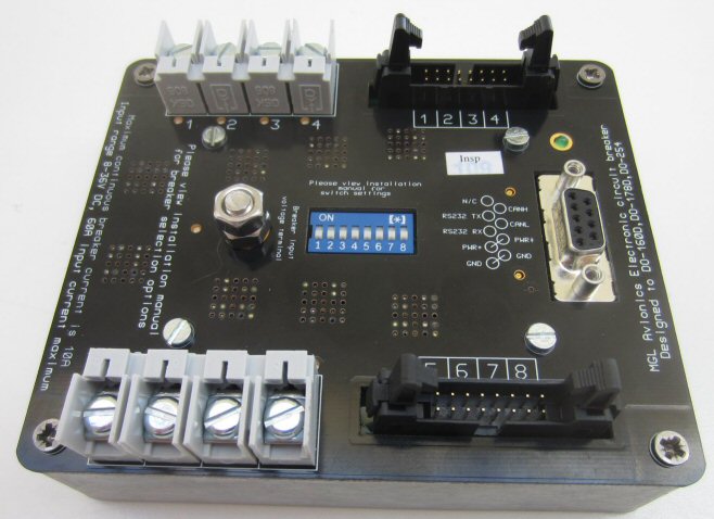
8 equal breakers, fully protected against all possible eventualities including reverse polarity, over current, over temperature. We use rugged high side switches intended for 24V truck applications, automotive grade. Bullet proof.
Each breaker capable of 10A continuous DC current.
Breaker doubling and tripling feature to create breakers of 20A and 30A capability.
Fully self contained unit, operates stand alone or as EFIS peripheral. Can be fully setup and programmed using only the dip switches, no laptop or EFIS needed.
Choose from up to 31 premade "profiles" using the dip switches which set trip currents, trip times and advanced features such as breaker doubling, tripling as well as "wig-wag" (alternating landing light on/off switching).
Typical breaker trip currents range from 1A to 30A (for a triple breaker). Can be set in steps of 0.1A if unit connected to an EFIS and the "programmable profile" is used.
Each breaker output as well as voltage input terminal have an LED indication on the ECB itself - a handy feature during installation and systems testing or fault finding.
If connected to an EFIS via CAN, EFIS can switch breakers and show breaker states as well as individual currents through each breaker.
The guiding principle behind this design is to allow full breaker operation (switch on, off and ultimate trip at 15A) in case of complete internal processor failure.
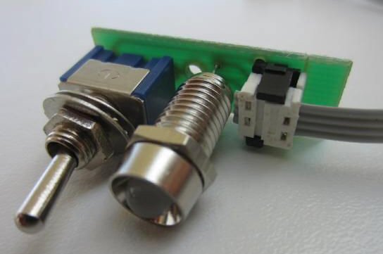
The ECB is essentially in two parts. The ECB module itself and an optional switch kit (this requires final assembly by the installer).
Purchased on its own the ECB contains connectors and a long piece of flat ribbon cable and you supply low current switches (any type as long as they are latching) as well as either one or two LEDs per breaker (depending on how you prefer the indication to work).
The optional switch kit contains 10 sets of PCB, dual color LED (red+green), toggle switch, chromed LED bezel, one set of 4 way crimp plug and socket. 8 sets are needed, 2 sets are included as spares. This kit requires soldering the parts onto the PCB.
LED indication can be set to operate in one of two ways:
1) Single LED. On if breaker on. If breaker trips, LED flashes rapidly until switch is switched of (which also resets the breaker).
2) Dual color LED. Green LED reflects switch status on/off. Red LED shows breaker tripped. This gives a third color: Orange meaning switch on and breaker tripped.
Switches are always the source of breaker states (on/off). Even if the EFIS is set to switch the breakers. In this case the switch must be "on" or if no switch is desired, you need a simple wire bridge.
Up to 8 ECB modules may be used in an EFIS system giving a total of up to 64 usable breakers, enough for even larger aircraft. No limit for stand-alone ECB installations.
This unit makes a good alternative to traditional mechanical breakers even from a cost point of view. Major advantages are effectively unlimited life, precise current trip points and defined trip behaviour regardless of ambient temperature.
Simplification of installation is possible as all high current switching may now be done at location rather than having to wire high current conductors to the panel. Each ECB comes with around 20 feet of flat ribbon cable for switches and LEDs, more than ample.
Specifications
- Breaker
- Maximum continues DC current through each breaker: 10A
- Maximum current through each breaker: 45A (ultimate trip current)
- Maximum die temperature of each breaker: 165 degrees Celsius. Breaker will switch off when reaching this temperature.
- Breaker clamp voltage:
- 65V (if input voltage rises above output voltage by 65V the breaker will start conducting and attempt to clamp the voltage at 65V in order to protect itself.
- Trip currents depend on selected profile.
- Trip times for profiles other than profile 31 (programmable profile) are fixed to 0.5 seconds multiplied by the inverse of the over current ratio. For profile 31 trip times are programmable from 0 seconds in steps of 0.01 second.
Example: Breaker trip current = 5A, trip time 0.5 seconds, breaker current = 5A. Trip time = 5/5*0.5 = 0.5 seconds
Example: Breaker trip current = 5A, trip time 0.5 seconds, breaker current = 10A. Trip time = 5/10*0.5 = 0.25 seconds
Example: Breaker trip current = 5A, trip time 0.5 seconds, breaker current = 20A. Trip time = 5/20*0.5 = 0.125 seconds
Currents during the over-current time period are integrated accordingly.
Breaker features “soft start” to protect equipment from sudden rise of voltage.
- Soft start characteristics:
- Turn on time to 20% of Voltage: 35uS typical.
- Rise time from 20% to 80% of Voltage: 17uS typical.
- ECB module general
- Maximum total continues input current through input terminal: 60A
- Maximum total instantaneous current through input terminal (1 second): 150A
- Maximum voltage with respect to ground on breaker input and output: 35V DC
- Supply voltage for ECB (on D9 connector): Maximum 35VDC.
- Supply current @13.8VDC is under 50mA.
- Note: Supply current for ECB will be taken either from the breaker input terminal or the supply
pin 4 on the D9 connector depending on which voltage is the higher.
- Control interface
- Switch current (switch closed): 3mA
- Switch voltage (switch open): 2.6V (up to 3.3V if zero load).
- LED outputs
- 3.3V via 68 ohm resistor into anode of LED, cathode at 0V.
- Typical currents depend on LED threshold voltage and are in the order of 20mA.
- RS232 port
- Baudrate 38400, 8 data bits, 1 stop bit. Daisy chain topology if more than one breaker used in system.
- Up to 8 ECB modules in a daisy chain.
- Please contact us if protocol information is required.
- CAN port
- Implements CAN 2.0 with 11 bit identifiers at 250KBaud. Up to 8 ECB modules may be connected to one CAN bus.
-
- Weight: 360g approx.
- Dimensions: 150 x 120x 48mm approx.
Ref : MG_ECB Electronic Circuit Breaker
Ask for a Catalog/Price list
Download ECB manual(French): ECB_FR_w.pdf
Download ECB manual(English): ECB.pdf
Top of page
|
|
Flaps/Trim Controller MGL SP-10
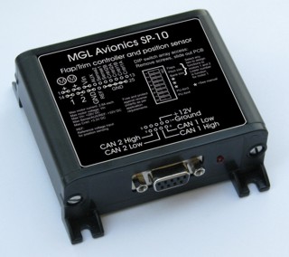
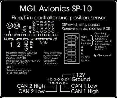
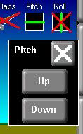
The SP-10 Flap and Trim controller is used with MGL iEFIS systems. It can also be used as a stand-alone 4 position flap controller.
The SP-10 provides two independent H-bridge motor controls, each capable of delivering 2.8A of DC current. If the SP-10 is used in single motor mode, the SP-10 can deliver 5A of current to the motor.
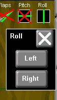
The SP-10 is used primarily as a 4 position flap controller, a pitch trim controller and a roll trim controller. Either two functions or a single function may be selected by means of an internal DIP switch array.
The SP-10 provides two position monitoring functions. These are used as flap or trim motor position monitoring for display on an EFIS or compatible system.
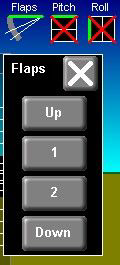
For the flap controller function the position feedback is used to position the flaps in one of four positions (Flaps up, flaps mid 1, flaps mid 2 and flaps down).
It is possible to connect the SP-10 to two independent external control sources such as an EFIS and a panel mount controller for example. Two independent CAN bus interfaces are used for this.
Up to 4 SP-10 units may be connected to a host system via CAN bus but in practice a maximum of three will be used as three functions can be defined.
Specifications
- Maximum motor supply voltage: +28V DC
- Motor supply ground = SP10 supply ground.
- Maximum motor supply current: 2.8A DC per motor output (limited to 3.0A maximum – motors with larger current demand may be connected but current will be limited to set maximum).
- Maximum voltage on sense 1, sense 2 , AUX and REF pins: 32V.
- Maximum voltage on Cntrl1, 2, 3 and 4 lines: 3.3V.
- Supply voltage range for SP-10: 8-16V DC
- Supply current for SP-10 (excluding motor current): 60mA at 13,8V DC.
- Connecteur DB-9 solide simplifiant installation et inspection
- Two independant CAN interfaces
- Weight: 120g approx
- Dimensions : 88 x 88 x 32mm approx.
Ref : MG_SP-10 Flaps and Trim controller
Ask for a Catalog/Price list
Download SP-10 manual(French): SP-10_FR_w.pdf
Download SP-10 manual(English): SP-10.pdf
Top of page
|
| CAN Interface for GARRECHT | |
|
MGL Stratomaster CAN Interface for GARRECHT Avionics
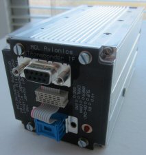 This solution provides a simple to use interface for a Garrecht Avionics VT-0102 transponder.
The VT-0102 transponder is connected to a compatible EFIS via CAN interface. The following EFIS systems are compatible:
- Voyager G2, Odyssey G2, iEFIS Discovery, iEFIS Explorer, iEFIS Challenger.
- Connection to Voyager G2, Odyssey G2:
Connect to the built in CAN interface port if no other items are connected to this port. In the EFIS setup, select "Garrecht transponder" as option for the CAN interface.
If the CAN interface is used to connect other items (MGL autopilot servos, AHRS, compass, RDAC etc), you must use a MGL Avionics "MG_MG198" CAN-CAN bridge unit or a "MGL REM-T1" remote control head to connect the Garrecht transponder to the EFIS. This provides the required protocol isolation between the devices. It is not possible to use the Garrecht transponder AND a MGL CAN bus device on the same CAN bus without a protocol isolator.
- Connection to iEFIS Explorer, iEFIS Challenger:
Connect the Garrecht transponder to any CAN bus on the iBOX unit.
- Connection to iEFIS Discovery "Lite":
Connect the Garrecht transponder to the CAN bus.
Download Garrecht Avionics transponder interface user and installation manual (PDF)
Dimensions: 65 x 65 x 25 mm approx
Weigth : 80g approx.
Ref : MG_MG198
Ask for a Catalog/Price list
Top of Page
|
MGL Stratomaster CAN Interface for TRIG Avionics
 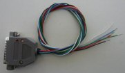 This solution provides a simple to use interface for a Trig Avionics TT21 or TT22 transponder.
This interface simply plugs into the rear of the transponder and typically only 4 wires have to be connected:
2 x CAN bus wires, power and ground. An optional suppression line is also provided should that be needed.
You do not need the NMEA feed to the transponder anymore, the GPS data is now sent via the CAN as is the state of the squat switch the operation of which you can configure in the EFIS.
The EFIS GPS/NMEA setup menu settings can affect what GPS information is sent to the transponder. If you have flagged an external GPS to be available (ARINC or NMEA) and it is flagged as a certified GPS and it is giving a valid position - then that GPS information is sent to the transponder and the EFIS internal GPS used as a backup (only for transponder use).
Please note that this interface does not work with the similar looking Dynon transponder. It is designed to be operated with the Trig transponder.
Download Trig Avionics transponder interface user and installation manual (PDF)
Dimensions: 55 x 45 x 18 mm approx (DB25 connector)
Weigth : 50g approx.
Ref : MG_MGL238
Ask for a Catalog/Price list
Top of Page
|
|
SP-12, 14 CFR §91.227c, AC 20-165B, Appendix B compliant GPS receiver
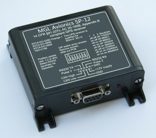
The SP-12 is based on the Aspen Avionics NexNav Micro-i GPS module used by several avionics manufacturers.
It provides a simple and low cost solution to the FAA 2020 mandate.
It provides the standard Micro-i NMEA output on RS232 but adds user selectable baudrates (the default is the standard 115200 baud used by the Micro-i module).
In addition it packs the NMEA data from the Micro-i onto the CAN bus for direct use by an MGL EFIS or compatible transponder without the need for further wiring. (Only the Trig transponder via the MGL Avionics interface is compatible at this point). The MGL Avionics T-16 transponder is of course also supported (this device is currently in development).
If you are using an older version of the MGL interface to the Trig transponder it requires a firmware update to support the SP-12.
This firmware can be downloaded on
this page
with update instructions.
Interfaces :
- 1 CAN interface
- 1 serial interface
Weight: 140g approx.
Dimensions : 90 x 70 x 31mm approx.
Ref : MG_SP-12
Ask for a Catalog/Price list
Download iExtender manual(French): SP-12_FR_w.pdf
Download SP-12 manual(English): SP-12.pdf
Top of page
|
MGL Stratomaster CAN Convertor
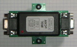 Connect a RS-232 or CAN bus to MGL EFIS (XTreme, ENIGMA, VOYAGER, ODYSSEY)
Converts RS-232 or CAN signals to EFIS RDAC format
Get engine parameters directly from the injection module
Example at ADEPT airmotive
Requires injection module protocol documentation
Contact us for a quote
Dimensions: 100x 31 x 32 mm approx. (58 mm wide with mounting flanges)
weigth : 50g approx, 80g approx. with two DB-9 connectors
Packaged with two male DB-9 connectors and shells
Réf : MG_uCAN
Ask for a Catalog/Price list
Top of Page
|
|
Colour Camera
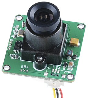
Colour Camera compatible with video input(s) of EFIS (Voyager/Odyssey G2) and iEFIS (Explorer/Challenger).
- Power Supply: 6 to 20V DC
- Consumption: 50mA (@12V)
- Resolution 728 x 488 pixels
- NTSC output
- Quality optics
- Weight: 20g approx.
- Ref : MG_CCAM
- Ask for a Catalog/Price List
Top of Page
|
|
Thermal Imager
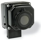
Low cost, compact Enhanced Vision thermal imaging camera for Experimental and light sport Aircraft
Allows you to see terrain, obstacles, and other aircraft in reduced visibility conditions including through smoke, haze, and light fog –
even in total darkness. It not only provides detailed video imagery of rising terrain and the entire runway environment, but also lets you see
people, animals, and vehicles on active runways and taxiways
Single-component unit that comes with an adjustable mounting bracket and an all-in-one “power-in, video-out” cable for trouble-free integration. Its composite video output connects directly to most display screens that have an auxiliary video input, requiring no bulky extra black boxes for minimal weight-and-balance impact.
It connects to
LETS PILOTS
- Maintain situational awareness in decreased visibility.
- See more of the runway environment, night and day, in good weather and bad.
- Reduce the risk of CF IT (controlled flight into terrain).
- See power poles, trees, and other obstacles from farther away.
- See better during “brown out” conditions.
- Identify rising terrain earlier.
- Detect runway and taxiway incursions – see animals, people, vehicles, and aircraft.
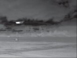
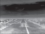

Thermal Imaging Performance
- Sensor Type : 320 x 240 Uncooled Microbolometer
- Field of view: 36°Horizontal x 27° Vertical
- Spectral Band: 8-14 microns (LWIR)
Video
- Outputs: NTSC &t PAL
- Frame Rate: 7.5Hz NTSC & 8.3Hz PAL
- Orientation : Invertible Image Option for Integration Flexibility
Power
- Power Requirements: 9 to 16V DC
- Power Consumption: <2W (<5W with heater on)
Environmental
- Operating Temp: -40°C to +80°C
- Weather Resistance: Hermetically Sealed
- Window: Impact-Resistant Optic with Built-in Automatic Heating Element
- Dimensions : 57.4 x 71.4 x 84.7 mm (2.3” x 2.8” x 3.3”)
- Weight:
- Camera : 363 grams approx.
- Adjustable mounting bracket: 200 grams approx.
- Wiring Harness (6 meters): 400 grams approx.
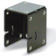
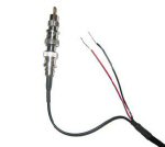

Réf : IR_Cam_Kit
Equipment described herein may require US Government authorization for export purposes. Diversion contrary to US law is prohibited.
Ask for a Catalog/Price list
Top of Page
|
MGL Stratomaster Comms Extender
 This module is not available anymore.
USB "COM Extender"
This device extends the number of RS232 serial ports for ENIGMA, VOYAGER and ODYSSEY EFIS systems to a total of six ports (two are available on the EFIS).
In addition this unit includes the servo interface section of the integral autopilot and it provides as part of this four PWM outputs that can be used with servos that accept this type of signal.
The COM Extender is simply connected to one of the USB host ports of the EFIS system using a standard USB printer cable (included or use your own), no further setup is required other than assigning functions to the varous ports from within your EFIS setup.
4 COM ports
4 PWM (Pulse Width Modulation) outputs
Used to interface EFIS to:
- TRIO GOLD STANDARD servos for Automatic Pilot
- Serial equipment like PCAS, weather receivers, etc…
Dimensions : 21 x 4.5 x 3 cm approx.
Weight: 150g approx.
Download the manual(French): Installation manual Com Extender(.PDF)
Download the manual (English): Installation manual Com Extender(.PDF)
Ref : MG_Comm_Ext
Top of Page
|
MGL Stratomaster Airtalk I/O Extender
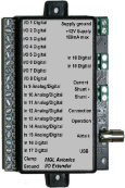 Airtalk Input/Output Extender
Expand acquisition and control capabilities of ENIGMA, VOYAGER, ODYSSEY.
This small unit extends Enigma with up to 19 digital inputs, 8 digital outputs, 7 analog inputs and a bidirectional current sensing system (intended to show battery charge/discharge current rates).
Connects to EFIS with a simple "Airtalk" cable.
The digital inputs are 12V compatible and can be used to create passive indicators (such as door open/closed, gear up/down etc) as well as alarms upon activation. The inputs can also be used as remote controls for the Enigma remote control popup menu which allows control over vital functions using just three (or four) buttons (perhaps mounted on a joystick).
Digital outputs are current sink outputs which can be used to control alarm annunciator panels, grouping classes of alarms (for example fuel level alarms) to an output. These outputs can be further used in a form of automation where you can program digital outputs to respond to analog input values (for example, switch on a fan if a certain level output from a
temperature sender is received).
Analog inputs are 12V inputs used to measure a voltage level from 0V to 12V. This can for example be created by a linear potentiometer coupled to a flap lever. Typical uses are: Flap and trim position indicators, fuel and oil level indicators.
Four of the available analog inputs can be used to activate standard Enigma alarms (subject to normal Enigma alarm routing).
Analog inputs can be associated with any Enigma analog display instrument (bargraph etc) complete with upper and lower warning and alarm limits.
The I/O extender ships with a graphic configuration utility that allows simple configuration of the functions required for the application. This exports a single script file which can be installed into Enigma (Common Tasks menu).
8 digital Input/Output (channels 1 to 8).
- Input : Inputs are considered high level at about 3.5V, low level below 2V. Compatible with 12V. Inputs are weakly pulled down with generous noise filtering. You can for example wire a switch between +12V and any digital input.
- Output : Digital outputs can switch 0.5A to ground (maximum rating 1A).
7 analog inputs (channels 9 to 15). Analog inputs have a 0-12V range with a 10 bit ADC resulting in values from 0-1023. Can also be uses as digital inputs similar to channels 1 to 8.
4 digital inputs (channels 16 to 19). Similar to channels 1 to 8 inputs.
1 "Shunt" input. Used to measure current across a shunt. Configure for any shunt or current range values.
Download manual: I/O Extender manual
Ref : MG_IOExt
Ask for a Catalog/Price list
Top of Page
|
|
|
|
 |
 |
 |
 |
|
|